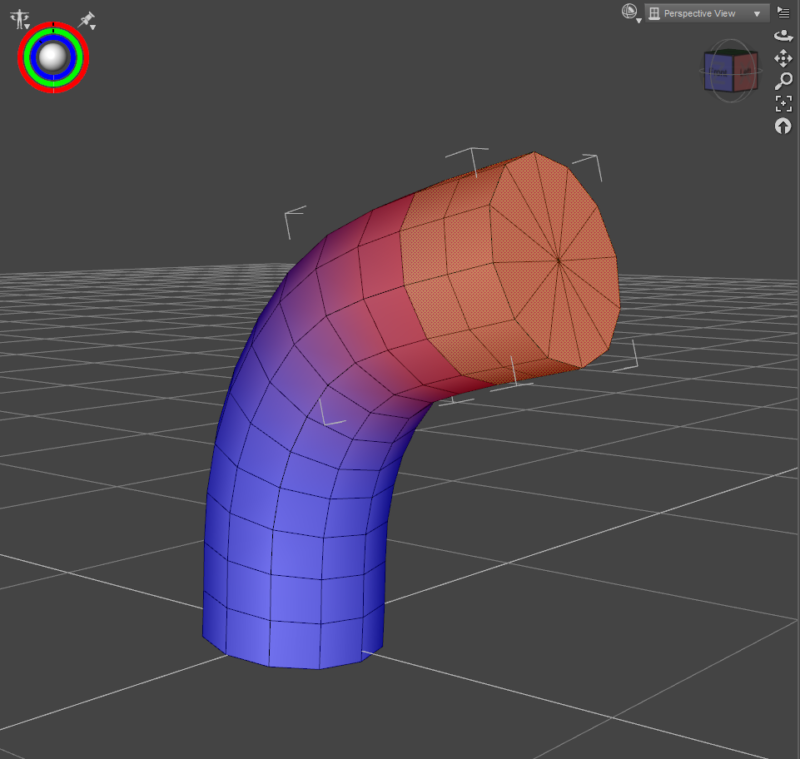
Believe it or not, the above picture is the result of trying and failing to understand rigging in DAZ Studio for years. I’ve had many attempts at understanding the official documentation on this subject, but severe lack of knowledge and understanding have kept me from transferring this information into my brain. Like many things, it’s not actually all that difficult to comprehend. Perhaps with this simple list of steps, we’ll all be able to build on the basics and remember how to get started next time.
Note that there are two types of rigging things in DAZ Studio: with the Figure Setup Tab, which will generate bones from the polygroups of an object, and by creating bones manually. I’ll explain the Figure Setup version here and will leave the manual bone creation for another article.
Creating and preparing my object
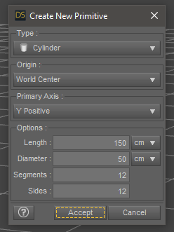
For this example I’ll do everything inside DAZ Studio so we’re all on the same page. Let’s make a simple cylinder primitive. I’ll choose one with 150cm height, 50cm diameter and 12 sides/segments. This will space out the geometry into easily selectable squares. I’ll enable the Wire Texture Shaded view so I can see my geometry.
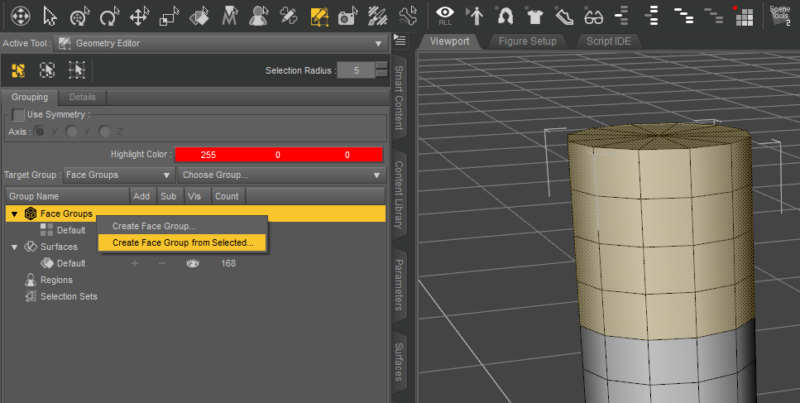
Let’s switch over to the Geometry Editor tool and create three polygroups for the top, middle and bottom parts of my figure. To do that, select the polygons you want grouped, left-click onto Face Groups, then right-click on that heading and choose Create Face Group from selected. Give it a name and repeat for all other groups. All of these options will appear on the Tool Settings tab.
For my example I’ll end up with three groups like this:
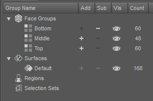
We need to save our object as OBJ file now, but these groups will stay intact. Head over to Export – Wavefront OBJ and choose the DAZ Studio preset.
It is very likely that on a real life object (i.e. not a cylinder), you may have similar groups already setup on your model. If they’re material groups, select and convert them. What DAZ Studio calls Face Groups is called different things in other 3D apps. Blender for example calls them Vertex Groups, while ZBrush calls them Poly Groups. Regardless, with these “zones” defined and exported as OBJ, they’ll stay intact and we’ll be able to infer bones from them in the next step.
Using the Figure Setup Tab
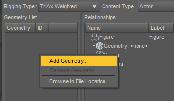
Save your scene if you like, then remove the cylinder so that we have nothing in our viewport. Open something ever so slightly intimidating called the Figure Setup Tab (Window – Tabs). On the right hand side, in the empty column labelled Geometry, right-click and choose Add Geometry. This will allow us to import the OBJ file we’ve created previously.
This next step is a little confusing: we need to drag our object from the left side over to the right side, onto the Geometry cube. It’s tricky to explain exactly so I made a GIF:
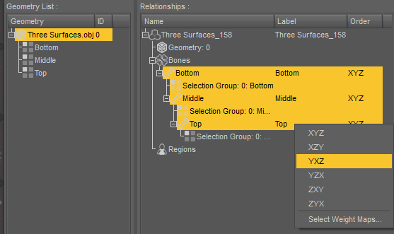
Once it appears on the right, you’ll see each face group in the hierarchy as a list of bones. In my example, all groups are on the same level, but I’d like for them to appear as child objects as if they were a figure. To do that, let’s left-click and drag one on top of another: Middle onto Bottom, then Top onto Middle. Again it’s tricky to explain in words, especially where to click. Here’s what I mean:
Our next step is to set the Bone Rotation Order. For me that’s the part I used to struggle with most, simply because I couldn’t comprehend what it meant. Let me try to explain how I remember them now:
The first axis is the “twist axis”, around which a bone rotates. The first letter denotes what axis the bones should be aligned with. For my upright standing cylinder, or the legs of a character, it’ll be the Y axis (so the rotation order will be YXZ or YZX). If you think about the bones of a fish or the tail of a dinosaur, it’ll be along the Z axis (so it’ll be ZXY or ZYX).
The second axis is the one that least likely reaches a 90 degree rotation, while the third axis the one that most likely reaches 90 degree rotation. On my cylinder the order doesn’t matter, but for a human leg the order would be YZX. For our fish and tail example it would be ZXY. From what I understand, the second/third axis isn’t as critical as the first.
To change our bone rotations, right-click on the bone in the order column until the menu comes up. You can select multiple bones too, if you want them to be aligned in the same direction.
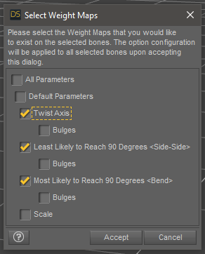
We’re nearly ready to create our figure, there’s just one more thing to add: the weight maps. Select all bones, then right-click again in the order column and pick Select Weight Maps at the bottom of the menu. This will add basic weights and maps, but we don’t need all of them. I’ll de-select the bulge and scale maps to keep it simple.
That’s it for the setup. Hit Create Figure at the bottom of the Figure Setup Tab and you’ll see a new rigged object in your viewport, complete with node hierarchy and bones.
Filling Bone Selection Groups
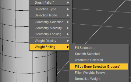
Although we have maps and bones in place, our nodes don’t seem to move our figure around. Try it out by selecting a node, then rotating it. Although the bones move, our geometry does not deform. The easiest way to make that happen is by selecting the Node Weight Map Brush tool, then right-click on our object and choose Weight Editing – Fill by Bone Selection Groups.
When done, switch back to your Universal Manipulator and rotate some of your bones and your figure should move with them. Hurra!
At this point, all of my DAZ Studio installations seem to develop a weird bug with the current version of 4.15.0.14: the figure does not deform while I move it. It will snap into place when I let go of my mouse button, and it will work just fine when I restart DAZ Studio. If you have the same issue, don’t worry about it. I’ll just save my scene and restart so we’re all on the same page.
In the next article I’ll have a look at how we can adjust the maps to make our object bend a little better. There’s a lot more to rigging that this brief overview, but it’s a start. Have fun!
Good day,
I am wondering why I could not drag my geometry from left hand side of figure setup into the right hand side section. I have attempted a number of times using different geometries. However, red error signs were seen. Appreciate your assistance.
Hi again,
Please disregard my pervious message. I have already fixed the problem.
Have a good weekend
Piroz
Great, I’m glad you’ve solved it 🙂
Hi Jay,
Thank you for your response. In your example of cylinder, the distorted cylinder looked well connected. However, parts of my geometry when distorted became separated. I mean that gaps can be seen between different parts of distorted geometry. Your assistance in fixing the aforementioned problem is highly appreciated.
Best wishes
Piroz
This happens when the mesh isn’t welded at intersections. As an example, clothing made from patterns can be merged or un-merged, which means that a welded/merged edge will stay intact while an un-merged/unwelded edge will break apart. You can weld retrospectively in Blender by using its “remove doubles” feature. Let me know if this makes sense, if not I’m happy to elaborate more.
Good morning,
You have used Edit-> object-> Geometry -> triangulate to smooth your object. My object does not contain geometry with quadrilaterals. In addition, the other option such as detriangulate appears to be unsuitable for smoothing my object. Do I have any other options to smooth my object?
You assistance on this matter is greatly appreciated.
A subdivision surface modifier will make your object look smoother (under Edit – Object – Convert to SubD). Note that if an object is not braced properly with edge loops, this operation can lead to a geometry collapse. For example, a default cube made of 6 faces will turn into a sphere unless edge loops are added to avoid this.
By the way, triangulation does not smooth an object at all and is not used for that purpose, instead it creates predictable triangles in existing geometry. Under the hood, ever render engine can only reflect light from a planar face, and such surfaces can only be guaranteed with triangles, so the render engine runs a triangulation pass no matter what the object looks like. However, this can lead to unpredictable surface cuts, especially with n-gons. Manual triangulation avoids this.
Hope this helps!